
The second year project for the students in the faculty of Electrical and Electronic Engineering consists of developing a line following robot that must complete a course at the end of the year with a good timing. The challenges on this course were set to increase in difficulty every year of the program. Back in 2013, the challenges were to navigate the course by following a white line which is not continuous and stop within a set distance from the end of the track. The white line could break along the direction of the track or laterally. The line follower should also be able to climb and decent slopes. To give an idea of the project below is a quick video which was made by the university.
Mechanical Design
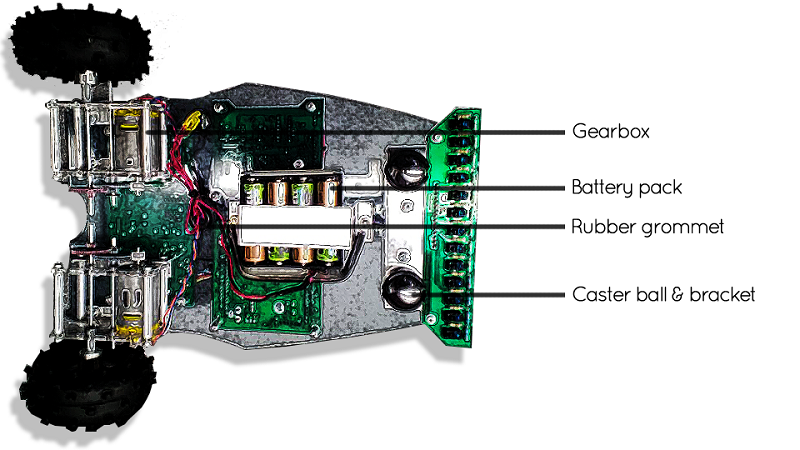
To optimise the performance of the buggy on the track, a correct balance must be maintained between the speed and torque generated by the motor and gearing. Using the motor that was provided by the university, a motor characterization was done to identify the torque provided by the motor. This was then coupled with approximated weight of the line follower to obtain the ideal gearing ratio specification that would need to be designed.
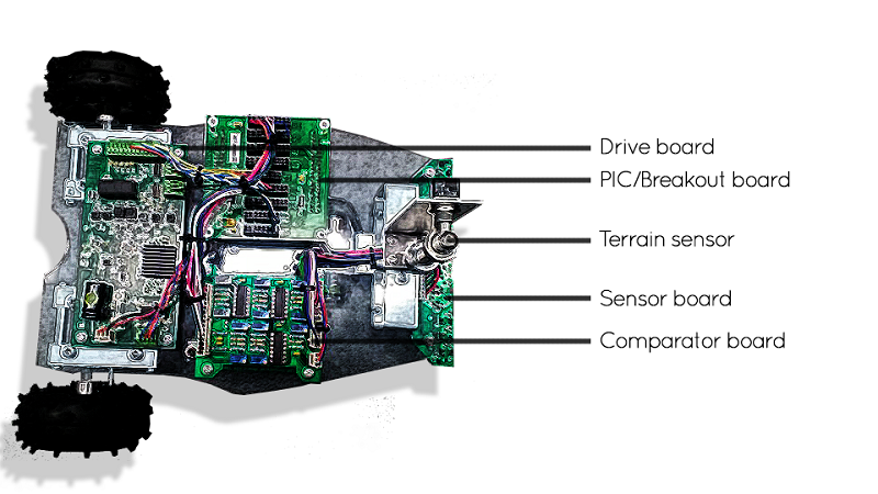
Sensors and Navigation
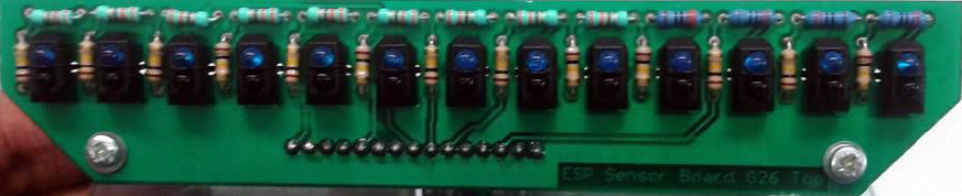
By taking in to account all possible scenarios on the track, I was tasked to come up with the sensor array and the navigation strategy. And of course I came up with the most absurd sensor design which consisted of 13 sensors. The idea at the time being that the sensor in the middle would be always on if the buggy is following the line correctly. The two sensors on either side were configured as analog sensors to make finer adjustments when the buggy moves off track. These 2 sensors would continuously influence the motor speeds to keep the buggy on track. The remaining 10 sensors on each side were configured as digital sensors and will only serve to make drastic changes to the navigation of the buggy if a line change was detected.
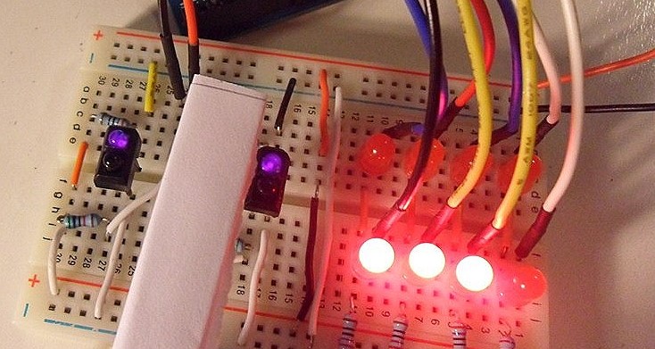
However, before coming up with this glorious sensor array, I was tasked with demonstrating the sensor array to the team and supervisor. This was done with a simple arrangement shown below which lights up the power difference sent to the wheels of the buggy based on the placement of the buggy with respect the white line.
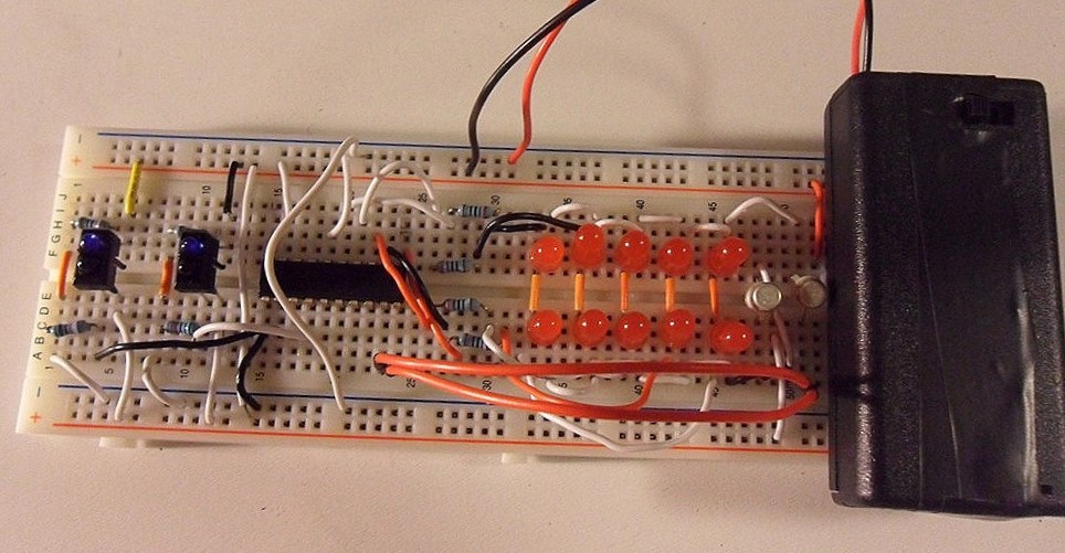
In terms of control system, at the time when starting out with the subject my choices were bang-bang control and PID and logically I selected PID control to control the speed of the motors based on the sensor output.
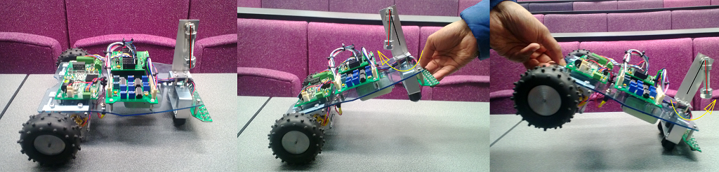
Additionally we designed another sensor to detect whether the buggy was climbing up or decending a slope. We came up with a novel sensor idea which uses gravity to change the resistance on a single turn potentiometer. This sensor design posed a lot of problems initially when dealing the oscillations due to accelerations and decelerations. However, after experimenting with a number of dampening methods and software debouncing methods were were able to get a decent result which allowed us to detect slopes and increase the power or decrease the power that we send to the motors. This design eventually won the team the award for the most innovative buggy.
with a ton of testing...
correcting...
more testing...
and some wins and loses...
I was getting closer...
...and then it was demo day!
Happy to say we aced the course in our first safe run, but unfortunately the buggy was not able to complete the course in the speed run for the team to secure a spot in the final races. But we did get this FPV from the buggy.


